Implementation Tasks
Data Modeling
Schneider Electric and Esri provide industry standard data models that provide a starting place for your ArcFM implementation. It may be the case that one of these models will work completely as-is to meet your needs. Typically some modifications and/or extensions are required.
The ArcGIS Electric Model
The Schneider Electric Multispeak Data Model
The ArcGIS Gas Distribution Data Model
The Schneider Electric Fiber Manager Data Model
Data Migration Design
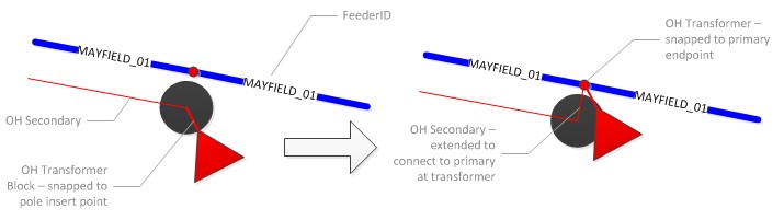
Like other tasks in your GIS implementation migrating data from your current map source into the ArcFM Geodatabase must be designed. Though a data source matrix spreadsheet is a critical component of a migration specification, a migration design is not simply a spreadsheet mapping source classes and attributes to target classes and attributes. It must also describe in words and pictures conditions present your current system and how they will be transformed to meet expectations of the new ArcFM implementation. Here’s an example:
OH transformers are snapped to the supporting pole insert point. The OH primary line is snapped tangent to the pole block. Within ArcFM connectivity will be established by snapping the transformer to an end-point of the closest primary with the same feeder and containing phases consistent with the transformer. This approach will maintain cartographic conventions similar to the current AutoCAD drawings while enabling connectivity within the ArcFM geometric network.
BSL has produced detailed data migration design specifications for dozens of ArcFM data migrations, including data from these domains:
- Electric distribution, transmission and substations
- Gas distribution and transmission
- Fiber optic networks
- Water distribution
- Wastewater collection
- Storm water collection
- Cadastral and planimetric land bases
Quality Assurance
Quality assurance in a GIS data migration has many components. Among the most important are feature count matching, ArcFM QA/QC rule validation, and network connectivity validation. Also important is matching of individual values from source to target.
To ensure a direct, unambiguous assignment of domain values from source to target database, whenever possible the domain in the target database will be defined identical in content to the corresponding source database. Exceptions will only occur with fields that have specific application-required values, an example of which is the “PhasingCode” field for electric equipment which ArcFM Feeder Manager always expects will contain values from 1 through 7.
To confirm that all coded value domains have identical codes and values in the source and target databases, BSL will perform an automated comparison process that will:
- Read all values from the source domain and test for an exact match in an entry in the corresponding target domain, and
- Read all values from the target domain and test for an exact match in an entry in the corresponding source domain
Having a correspondence between source and target fields and a correspondence between domains assigned to those fields, it will be possible for the quality assurance process to obtain counts of domain values present in the source and ArcFM database and in this way confirm that values have been assigned as expected. As implemented, this process stores class, field and domain correspondence information in an MS-Access database, the general structure of which is described in the figure below.
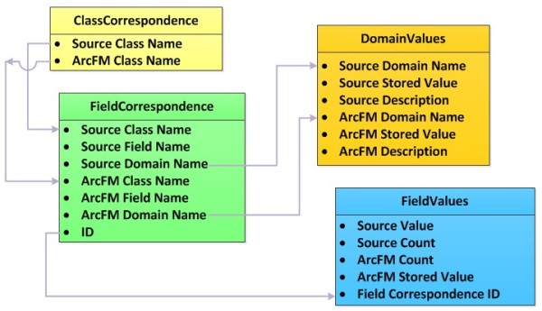
A QA process will use information in the table to, first, obtain counts by domain value for all values assigned to a field. Note also that the process will record the “stored” value for each coded domain pair. This value is what will be stored in the ArcFM database – and will be used in the subsequent QA step.
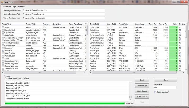
After the migration process has been completed the next step of this QA process will query the corresponding target classes and fields present in the new ArcFM database. The figure below illustrates the result of a test run performed on the same portion of a source database and shows counts for values in the source and the target fields. In this example all counts match for all domain values.
ArcGIS Electric Data Model
Originally the ArcGIS Electric Data Model conceived in 1999 to coincide with the first release of ArcGIS, this model was constructed by a consortium of utilities, implementers and consultants working closely with Esri staff. In general the modeling process followed a “kitchen sink” approach in which all types of equipment would be included with the goal that the principle effort of any implementation would likely be to remove those elements not needed or applicable. Historically the model has been maintained be the Esri Electric and Gas User Group (EGUG) community. Elements have been added to the model as suggested EGUG workshop participants as long as a plurality of attendees agreed it would be of general value to the community and not simply a requirement unique to one company.
The model contains an extensive set of classes, properties and relationships describing electric distribution equipment as well as basic characteristics for substation and transmission equipment.
Schneider Electric ArcFM Multispeak Data Model
The ArcFM Multispeak Model was built by Schneider Electric to coincide and support the National Rural Electric Cooperative Association (NRECA) Multispeak standard and to take advantage of ArcFM Solution functionality created specifically to address that standard. While many of its elements are common to the ArcGIS Electric Data Model the design approach is to provide for a standard core of electric distribution equipment that most small to mid-sized electric utilities need with little modification.
The ArcGIS Gas Distribution Data Model
Similar in origin and design philosophy to the ArcGIS Electric Data Model the ArcGIS Gas Data Model was developed at the outset of Esri’s ArcGIS software and has been maintained by the Esri Electric and Gas Users Group. This model uses the ArcGIS geometric network to represent pipes, regulators, valves, customer services and other appurtenances to the gas distribution network.
The Schneider Electric Fiber Manager Data Model
Along with the Fiber Manager product, Schneider Electric developed a standard data model to provide a starting place for Fiber Manager product implementations. While in other utility data models naming conventions for feature classes and attributes can be changed from implantation to implementation by making use of ArcFM Solution model naming conventions and in that way quite configurable, the Fiber Manager model is considered to be even more so since each class can be assigned model names that govern parent/child relationships. In this way the Fiber Manager model is considered a highly “flexible” data model that is well documented in SE resources material.