Transforming Smallworld Internal Worlds into ArcGIS
There are several reasons why you might want to move data from your Smallworld GIS database into an ArcGIS/ArcFM Geodatabase; you want to publish information from your production Smallworld instance data to Esri format for web publication, you have external customers who use Esri technology, or you’re migrating your system of record into ArcGIS/ArcFM. In any case there are a number of things you need to take into account, among them are dealing with multiple geometries than can be present in a Smallworld GIS class, coincident network features and features defined inside “internal worlds.” This last item is what we’ll address in this case study. In practice there can be variations that you’ll need to take into account for a specific transform process. Our goal here is to provide an introduction.
To review briefly, an internal world is a separate coordinate space in which features can be defined within the Smallworld GIS database. So, while your “external” system may be defined in a standard projected coordinate system, let’s say Colorado State Plane North NAD 1983, features in an internal world can be defined in page units and scaled and rotated independently of how they would be positioned were they to be mapped in the external world.
These are typically used for depicting details inside some type of container, such as an electric substation, a gas regulator station or electric switch cabinet – though the particular use depends on the needs and ambition of the Smallworld implementer. In our case we’ll use as an example of an electric switch cabinet.
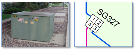
The external world network features are connected to the internal world by hypernodes. Each hypernode feature has a geometry in both the external and internal worlds but has a single unique identifier, so when a trace process comes along a hypernode it knows to jump from one world into the other.
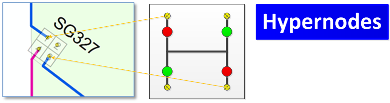
A standard strategy for representing internal world contents within an ArcGIS Geodatabase has been referred to as the “postage stamp” approach. Features from the internal world are transformed to fit within the external world spatial reference and connected at junctions created from the hypernodes. For display these are either scale suppressed or hidden by over-posted by the container polygon – such as the substation or regulator station fence or cabinet box.
Given that background and general strategic approach let’s talk about how we accomplish transformation. First, there are multiple types of transformations available to us that serve different purposes – the one we’ll want is an “affine” transformation. This will retain angles and proportions, but not necessarily connect all available hypernode locations. The affine transformation applies an X,Y transform (move), scale and rotate, but doesn’t “warp” geometries to obtain a fit. We’ll see the impact of this approach at the end.
The affine transform takes two points from the source coordinate space and two matching points from target coordinate space. As you can see from the example graphic above there may be (and often are) more than two hypernodes, so we need to get two from the N available. There might be different strategies for this depending on the specific nature of your data, but a simple approach is to just use those farthest from each other. One way to do this is the routine below.
Now that we’ve got our source and target points – in this case the lower right and upper left hypernodes in the switch cabinet — we need to create the transformation which, interestingly takes less code than getting out two points. The following routine takes in two internal node point feature and two external node point features and returns an affine transformation, ready to apply.
Once we have the transformation defined we need is to apply it to all features present in the internal world, and then of course repeat the process for all internal worlds. How satisfactory the transformation will depend in large part on how well the arrangement of internal and external hypernodes match. The following routine takes a source feature class and query filter, a target class and our previously created transformation and created transformed features.
So great, we’ve used internal and external hypernodes to transform features from the internal world to fit with within the external world container. We’ve maintained angles present in the internal world and found a good fit. In this example we’ve used illustrations from an electrical switch cabinet, but the contents could be gas mains, water mains, fiber cable or any other utility network feature.
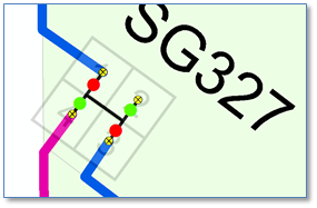
And in this example we’ve been lucky that the arrangement of internal and external world hypernodes has been very similar, so that the internal line endpoints snap nicely to corresponding external world line endpoints. But what if they didn’t? (And from experience we can attest that they sometimes do not.)
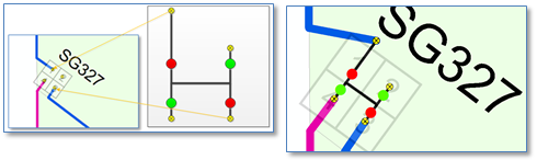
Below is an exaggerated example to illustrate the point. In this case the upper left node in the internal world is far offset from the location of its partner in the external world — meaning our transformation will result in a case where things won’t “just connect.” We may need to move (or extend) the endpoint of the internal world feature to connect to the external world endpoint or move (or extend) the external world endpoint to connect to the internal world end point. Shown at the right is an example of moving the external feature to connect to the internal.
Whether you’ll need to deal with this condition will depend on specifics of your source data. In any event, hopefully this was a helpful introduction to the internal world transformation process.