ArcGIS Utility Data Modeling: Why the Three Normal Position Fields?
In the standard ArcGIS Electric Data Model the fields on the classes Switch, Fuse, OpenPoint and DynamicProtectiveDevice are:
NORMALPOSITION_A
NORMALPOSITION_B
NORMALPOSITION_C
On the ArcFM Multispeak model the equivalents are:
PosA
PosB
PosC
And of course they indicate the status per phase on a switchable or protective device. But few other electric data management or analysis applications share this convention. Rather, most often a device that can be opened or closed to prevent or enable flow of electric power has a single STATUS field (or equivalent).
So, what’s up?
Well, what’s up is that the founding ArcGIS data modelers listened very closely to the user community when evaluating how to model these devices. If you’ve ever been in a conversation with an electric distribution system operator on the topic you might recall it going something like this:
Data Modeler: “As part of your normal practice do you ever change the status of one unit multi-phase device? Or feed a single multi-phase span from different feeders coming from different directions?”
Operator: “No. Our standard practice is to operate all phases together as a group.”
Data Modeler: “OK. Got it. But is there ever an occasion in a non-normal circumstance where you might, say, open one switch in a three phase bank and leave the other two closed?”
Operator: “Well… as part of an outage restoration process we might do something like that. But it’s pretty rare. And all switches in the bank should get restored to the same status when the restoration is complete.”
Data Modeler: “OK. Got it. And is it *always* the case that devices get restored to a consistent status when a restoration is complete?”
Operator: “Yes, always. Except we’ve still got a case like that down off of lower Broad Street for an outage last month. And now that I think about it there may be another one on the west side near 16th and Pine.”
… and so forth.
(You can tell this conversation was a simulation because the Modeler appears more insightful than the Operator. I practice it would be vice versa.)
So, while the practice of different statuses by phase in a single device is not a thing anyone would recommend – the modelers understood it’s a condition that can happen. Further, while one might be tempted to consider different statuses by phase in a bank a condition only of interest within an OMS or DMS, it can also be important for non-operational users of the GIS.
How does it work?
Now that we have some background on the model, let’s take a look at how applications take advantage of it. For this we need to call on ArcFM and specifically ArcFM’s Feeder Manager tracing capabilities.
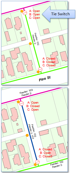
Let’s start with an admittedly simplistic scenario where we have an open feeder tie switch separating feeders 102 (green) and 103 (magenta). Two spans upstream on feeder 102 we have another normally closed switch – shown at the right. (In practice these might be fuses or reclosers and may be a good bit of distance apart from one another.)
Now, say there is a fault on a single phase, phase B, of the 102 feeder downstream from our second switch. We open the switch unit on phase B to clear the fault and correspondingly close the switch unit B on the feeder tie switch – resulting in a multi-feed.
And in this case, that’s what there is. The span in question is fed on A and C phases from feeder 103 and on B phase from feeder 102. And the span itself now is assigned 102 for FeederID and 103 for FeederID2.
That’s why – or at least one of the reasons why – the ArcGIS Electric Data Models have multiple normal position fields.
Further, to have your Geodatabase respond correctly to this combination of settings you need ArcFM and Feeder Manager.
Summary
Sometimes we’re asked “why three fields for normal position?” Hopefully this post has provided some background on the origin of the modeling convention and example.