ArcGIS Utility Data Modeling: URD Opens
Sometimes we can fall into the trap of thinking that a data model — maybe with a little configuration — is completely prescriptive of all that needs to be accounted for when building a Geodatabase. Of course this is not so.
While the data model provides a foundation in the form of table definitions an relationships, equally important are the behaviors and cartographic conventions we apply to make the Geodatabase work.
The case in point we’ll address in this post is the use of padmount transformer elbows and/or open points for indicating open locations in electric distribution URD loops.
Business Requirement
Underground Residential Distribution (URD) “loops” – the construction design convention for supplying most residential subdivisions since the 1960’s – are loop fed only in terminology.
In practice these components of the distribution network are, like most of the network, radially fed given that the “loop” includes one or more open locations that prevent you from getting back … as would be a requirement of a true loop.
Modeling Options
The most common conventions for representing these features — both supported by the standard data models — are:
|
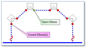
1. Mapping each individual elbow on the padmount transformer. |
|
|
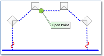
2. Mapping a single open point at the location where the elbow is put into the stand-off position. |
|
There’s not a right or wrong way to go about this. Your choice should really be based on what you’re trying to accomplish – both within your GIS and with applications that are fed from your GIS. So, here are a few of the business requirements we’ve seen that influence a decision. We’ll skip the most basic one, which is to accurately reflect network connectivity as the GIS network is traced.
• Updating the open point location. The position, or number of open points in a URD loop can change for a variety of reasons but typically it would be done for either planned or un-planned maintenance or to accommodate new construction. If the change is one than the your company’s GIS change window, then no update within the GIS may be required, but otherwise there needs to be a way to indicate a given open is now closed or vice versa.
|
GIS Change Window
Changes occur in a distribution system all the time. Many are temporary – very temporary like the initial open of a recloser when it first senses a downstream fault and then closes back in. This is a change that is in effect for seconds. Other changes are intended to be more or less permanent – like the energization/as-builting of a new subdivision. Given that the goal of most utility GIS databases is to maintain a representation of the “normal” state of the network, it’s pretty easy to make the call that the instantaneous recloser change would not require an update to the GIS but the subdivision addition would. The thing is, there are many change conditions that are not so clear. For example, what about the switching change to accommodate a construction project that is projected to last a day? Or for a week? Or for a month? Many companies have a “Change Control Board” which is a formal or informal group that makes a daily assessment of what changes will and what changes will not be reflected in the GIS. |
• Open point cartographic display. It’s important that people operating your system be able to easily see the open point location and quickly distinguish it from the many other elbow connections in the loop that are closed. Its typically insufficient to say, “the open point is where my trace stopped because it wouldn’t have stopped if there was not an open point”.
• Association with the containing piece of equipment. Open points don’t exist free-standing on the surface of the earth, like pole. They’re contained within a cabinet structure of some type. It’s important to what structure that is. If you’re going to dispatch a crew to that open point location, chances are you will need the identification number of that containing cabinet.
As we said, there is no right or wrong approaches, but here are some considerations on how the conventions we described above meet our identified business requirements.
| Requirement | Map Each Elbow | Map Single Open Point |
|---|---|---|
| Updating the open point location | If all elbows are mapped, then changing the location is simply a matter of updating the status of the open elbow to closed and changing the status of another elbow to open. If you provide data to an application where users can’t readily add or delete features but they can easily change a status attribute – such as Schneider Electric’s Responder – then this approach would be important. | This either requires a “move” where first the open is disconnected from the network, then moved and reconnected at a new location, or a “delete” and an “add”. |
| Open point cartographic display | When zoomed in to large scales visibility is clear. When zoomed out to smaller scales the symbol may be more difficult to see or collide with/obscure its containing cabinet feature. | The feature can be placed for convenient display at large or small scales. |
| Association with containing equipment | A relationship can be created from transformer to elbow, and since the elbow is typically placed in close proximity to the transformer feature the ArcFM Structure Relate auto-updater to establish and maintain the relationship. | With this approach the open doesn’t represent a particular piece of equipment, but rather simply that the network is open. You may choose to make a relationship from the open point feature to the cabinet – or simply rely on visual proximity to identify a containing cabinet. |
The “Both” Option
There is the point of view that whenever there is a choice between A and B the right choice is both. Of course this be carried too far, but in the specific case of URD open points it at least merits some consideration. In this case the single “OpenPoint” feature would not be a part of the geometric network but used for visualization when zoomed out to small scales only and the mapped elbows would be used for managing actual connectivity. The price is that both sets of features must be maintained.
Summary
The choice for how you model URD opens depends as much with requirements of the systems you feed from your GIS as with requirements within the GIS itself. Hopefully this post has presented enough of the advantages of each so you can make an informed choice.