ArcGIS Utility Data Modeling: Electric Distribution Transformers
It can be reasonably argued that the transformer is the thing that ultimately allowed Nicholas Tesla’s AC to win out over Thomas Edison ‘s DC in their War of Currents (and though we don’t normally provide literary reviews here, this is a really good book.) Within the transformer voltage is reduced (or increased) proportionally to the count of copper wire windings on the high and low sides of a magnetic core.
In the distribution system conductors carrying primary class voltage (typically 2 KV and above) are connected to bushings on the high side and secondary conductors (carrying 600 volts and less) are connected on the low side. So there’s a high side connection and a low side connection.
Which brings us to our GIS representation which in the ArcGIS model is a point with connected primary and secondary lines. You may be asking, how can a single point accurately represent a thing that has a high and a low side connection, right? We’ll get to that in a bit.
Traversing the electric network from primary to secondary (or secondary to primary) must proceed through the transformer. 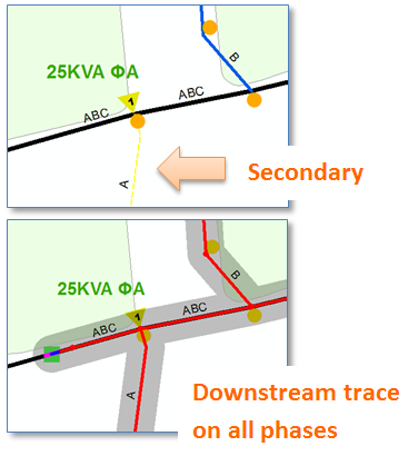 No big deal when both primary and secondary are 3 phase, or when both are single phase (and the same phase.) But in the common case where a single phase transformer is connected to a three phase primary we clearly need more information.
Let’s illustrate.
Say we’ve got a 3 phase primary with a single transformer connected to phase A providing single phase service to a downstream customer – as shown to the right.
If we’re tracing the network with the purpose of finding all connected customers regardless of phase, then again, no big deal. We trace from primary through the transformer down to the customer and we’re all good.
But say we trace with the purpose of finding customers connected to phase B, or phase C? In such a case the transformer actually acts as a barrier between the primary and secondary. Phase B doesn’t pass through the transformer and neither does phase C – through of course it passes through on the primary side.
How does our GIS model know this? 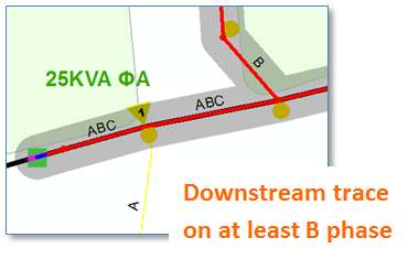
Well, you could say we would know based on the phase of the transformer – a trace on phase B should pass through a single phase transformer on phase A. However, this would cause the trace to stop at the transformer even for connected primaries – and that’s just not right.
Somehow the trace can distinguish the primary side of the transformer from the secondary side – even when the transformer is simply a point.
How? ArcFM tracing learns about the high and low side of a transformer based on the Operating Voltage of connected conductors. That’s how.
A consequence of this approach is that the assignment of operating voltage for each conductor feature takes on heightened importance. The following example offers a demonstration of how a NULL or incorrect voltage value on a primary conductor can cause unexpected results for an ArcFM trace operation. The figure below illustrates the case of a primary conductor span with a NULL operating voltage value.
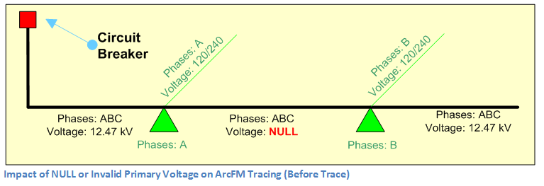
This span runs between two single phase overhead transformers, one connected to phase A and the other connected to phase B. On executing an ArcFM downstream trace, the trace will stop at the second transformer – making it appear that the transformer itself is stopping the trace, when in fact what has happened is that the trace found a line with a different voltage that the previous upstream line, considered it to be on the low side of the transformer, and permitted only phase A to proceed through.

The point is that ArcFM tracing is dependent not only on connectivity and phase designation, but also in the case of transformers, the primary and secondary voltage designations.
Now, we have to acknowledge that there are mapping conventions some companies follow to place the transformer offset from the primary with a connector of “jumper” edge that minimize the importance of operating voltages values for this type of tracing, but for companies that connect the transformer directly on the primary — and secondaries directly to the transformer the importance of operating voltage values is a handy thing to keep in mind.