Unexpected uses for an Electric Connectivity Extract
Recently we were asked to create a “Device Connectivity” table from an electric distribution geometric network. As the name implies, the table holds a record for each device in the radial network. That is, each breaker, recloser, switch, fuse, capacitor, regulator, transformer, etc., with the exact device classes and subtypes defined in a configuration file. As roughly depicted below each record contains the device type, unique identifier, the ID of its “parent” device and its “protective parent” device, where a “protective parent” is defined as the next upstream device that can operate to protect downstream equipment.
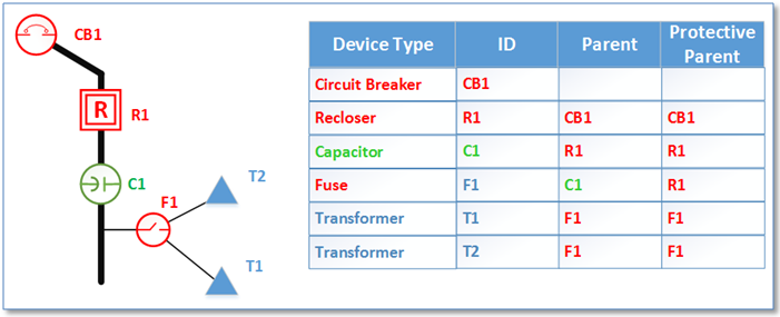
Figure 1: Device Hierarchy
In our case the business driver was a very specific requirement necessitated by functionality from a legacy application targeted for retirement. However, once the table was created and a process put in place to maintain it at regular intervals, other unanticipated uses started popping up.
In subsequent discussion with other utilities we’ve found this practice not to be unique. Though business drivers may differ.
You may never have thought of creating a company resource like a device connectivity table. However in this article we’ll talk about a few reasons why maybe you should.
Interface Validation
This one frankly caught us a bit by surprise. But once we understood the goal it was like, “of course!”
The central idea is this, if you have an even somewhat mature ArcGIS implementation you are exchanging data with other systems. This is the whole GIS-centric utility network management idea our friends at Esri have been promoting since, well, since there was a thing called GIS. In many cases you’re exchanging some representation of your electric network, either the whole system or a part of the system, like a feeder or a collection of feeders fed from a substation.
Turns out that there is more than one way to extract data from your electric network. And different vendors can (and do) use different approaches. In some cases the vendor (or interface implementer whoever they are) might simply do a selection based a field in each feature class – say the FEEDERID field – get a set of edges and junctions and determine what is connected to what based on simple geographic proximity.
In other cases the implementer may do a connected trace in ArcGIS that doesn’t take into account ArcFM properties such as Feeder Manager Non-Traceable or takes Enabled Field settings into account when Feeder Manager is configured not to. In either case (or other variations unmentioned) since the extract process uses a different method to determine what is connected to what than Feeder Manager there is a chance results may differ. Until you do a comparison you really just don’t know.
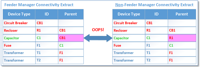
Figure 2: Interface Validation Example
An additional benefit we found in the process of testing this technique was that we were able to discover features that had unintentionally become disconnected. At the conclusion of processing all feeders we added a step that compared the full set of each device type with the set of devices that were found connected to a feeder. Those not connected to a feeder, and which were not expected to be connected to a feeder (based on an Enabled field setting) were included in our list for further review by the GIS maintenance team.
Non-GIS Based Customer Query
There may be many users in your utility that need to know about the distribution network, including users that don’t have access to the GIS – and to whom you may not want to provide access to your GIS. In fact, you may want to provide information that comes from your GIS but you don’t even want consumers of this information to know that it came from the GIS.
Such a case might be an applet in which a user provides a device ID and gets either a count or a list of customers downstream of that device. The business use case might be driven by a known outage or a planned outage, or even a simple “what-if” scenario.
In our case we created a simple web service – outside the GIS infrastructure – that returned a set of transformers downstream of a user-provided device. The consuming application then took this list and performed a look-up in the CIS database for all customers served from these transformers and returned results to the customer. Our goal was to provide a response within 2 seconds and testing found our solution to consistently meet this goal.
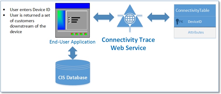
Figure 3: Connectivity Trace Service
“Tracing” in Applications that Don’t Provide Native Network Support
Some GIS-enabled applications use data provided from the production Geodatabase instance, but don’t have access to a “geometric network”. An example are applications built on top of Esri’s very popular ArcGIS Runtime technology.
In our case we worked with a mobile application that and supports of a full copy of the electric and land base datasets on each user’s mobile device. Updates are provided from the corporate Geodatabase by a synchronization process that operates when the user becomes connected to the corporate network.
With a simplified user interface, field crew users can easily navigate to any location in the service territory and view and interrogate the map for facility locations and attributes. Displays mimic corporate standards employed both in the desktop environment. Devices are GPS enabled and the mobile solution can follow along as the crew drives to a work location or patrols an area to be inspected.
The full-time access to the entire service territory, ease of use and range of functionality all plays well… but one function deemed vital to user acceptance was missing – the ability to trace the electric network to discover upstream and downstream equipment. While Esri’s ArcGIS Runtime technology has matured significantly since its release in 2013 it does not support all data structures that can be created in a traditional Geodatabase, including a geometric network.
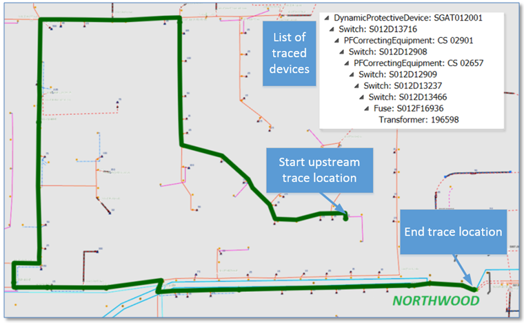
Figure 4: Example of Trace Upstream All in ArcGIS Runtime
Mobile tracing is provided as a tool that operates within the open framework ArcGIS Runtime – reading a copy of the device connectivity table synchronized to the mobile unit. A “Trace Upstream All ” tool walks upstream from child to parent, regardless of whether the parent device is protective (i.e., can operate to isolate downstream equipment in the case of a fault). The “Trace Upstream Protective” only looks for upstream protective devices, typically fuses, reclosers and circuit breakers.
Summary
We were asked to create a “Device Connectivity” table from an ArcFM™ Feeder Manager-managed electric distribution network to support a single, isolated business function. In the course of a year’s time we found and implemented multiple applications all taking advantage of the same table. Could have been a little serendipitous, but in our case the initial investment proved quite worthwhile.