ArcGIS Substation Details – Pros and Cons
In the early days of electric utility GIS when the discussion of including substation details was raised it was often the case that business drivers were not there to support it. The values for incorporating distribution (and sometimes transmission) equipment in a GIS included:
- Ability to apply updates rapidly – either as the result of system improvement or map corrections
- Ability to easily share updated information to end users throughout the organization, and
- Ability to exchange asset and network models with other enterprise applications, such as work management (WMS), outage management (OMS), system planning and asset management
Substation equipment didn’t really change that often, was created and maintained by a different part of the organization than distribution (and sometimes transmission), and was needed by a relatively small number of users. Further, unlike distribution data, there weren’t external applications that would readily benefit from substation details provided by a GIS. For example, OMS and system planning applications worked fine with an upstream source as the substation circuit breaker – or some approximation of it, such as a point where the feeder crosses the substation fence.
On this last point new advanced applications, such as distribution management systems — or as some prefer, advanced distribution management systems (ADMS) — are changing the electric GIS landscape. These applications do need substation details as well as the full distribution connectivity model. Which now raises the question, should utilities extend their GIS to incorporate substation details. That is the topic of this post.
Modeling Options
To cut to the chase, there’s not really a right or wrong answer to this question. Rather, it’s a question of what works best for the individual organization – and the tools available in the GIS and target applications. If you maintain substation details only in the ADMS then there will likely be an association between feeder circuit breakers that link the ADMS substation equipment to the downstream distribution feeder equipment.
If you do choose to incorporate substation details in your Geodatabase toward the goal of feeding an ADMS, there will likely be a number of modeling conventions you’ll need to take into account that you might otherwise not. Here are a few:
Transformer Winding Representation
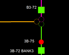 Like a SCADA display, ADMS representations will likely display substation equipment colored based on the nominal voltage rating – this includes bus bars as well as transforming and regulating devices. And for transformers where voltage is associated with a winding, there will need to be the ability to render high-side, low-side and tertiary windings in separate colors.
The example at the right shows 132 KV equipment in magenta, 46 kV equipment in green and 4KV equipment in gold. Since there will likely be additional properties distinct to the winding, as well as properties associated with the bank as a whole it may be the case that your model may include a bank feature, with two or three windings as child features related to the bank.
Analog Display Locations
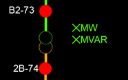 The ADMS will likely want to display near real-time analog information at standard positions within the substation display. If substation details are being provided by your GIS you may choose to define position and definition of such analog points as well.
At the right are examples of analog point locations at which MW and MVAR measurements for a given voltage level are defined.
Poke Points
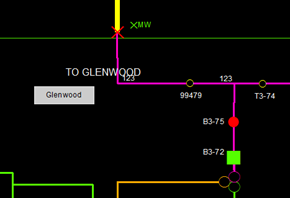 The ADMS will want to provide an easy way for a user to jump from station to an adjacent station without having to zoom out or zoom in. One mechanism for supporting this capability is referred to as a “poke point.” As the name implies, poking on the point will cause the display to jump to another display – typically another station.
In the image to the right clicking on the “Glenwood” box would jump to that station. These could be defined as simple polygon features in you GIS.
Addition Examples
A few additional examples that might merit consideration include:
- Temporary (mobile) substations
- Status display points
- Tag display points (though these could also be accommodated by symbology on the switching device within the ADMS)
- Equipment settings, such as capacitor and regulator control settings.
Additional features/objects required to support the ADMS connectivity model – clearly this would be dependent on the target ADMS.
What’s Best for Your Organization
Here are a few of the questions that might help guide your decision making process.
| Question | In the Geodatabase | In the ADMS |
| Geodatabase Maintenance Responsibility | The same processes, and possibly the same staff that maintain the distribution (and transmission) model(s) also maintain substation models. | The type of data and processes used to maintain it are sufficiently different that they should be maintained separately. Also, it may not be reasonable to expect that the staff familiar with requirements for maintaining the distribution connectivity model. |
| Data Ownership | Either ownership of substation details is assigned to staff currently maintaining distribution (and transmission) data, or permissions can be established in the GIS such that only authorized staff can update substation details. | Ownership of substation details lies only with staff with authority to access and update the ADMS database. |
| Frequency of Update | Additions and changes to substation equipment may occur and be accommodated in the same manner as changes to the distribution system. | Additions and changes to substation equipment occur relatively rarely. |
| Data Model Consistency | The GIS model is either consistent with the ADMS data model, or can be adjusted to match critical elements of the ADMS model. (By adherence to CIM modeling conventions this should nearly always be the case.) | Either aspects of the ADMS model cannot readily be defined within the GIS or it is inefficient or otherwise undesirable to do so. |
| Tools Available for Creation and Maintenance | Tools are available in the GIS to efficiently and accurately create and maintain substation equipment and the connectivity model required by the ADMS. | Tools within the ADMS are specifically defined for creation and maintenance of all substation equipment – and offer clear advantages over those present within the GIS. |
| Standard Interface Capabilities | The interface between the GIS and ADMS will effectively support transfer of all substation details and connectivity conventions from the GIS data model to the ADMS data model. | Either the GIS-ADMS interface will not support transfer of all substation details and connectivity conventions, or the process required to accomplish this is onerous. |
| Interface Performance | The GIS-ADMS interface will fully complete in a timely manner – probably as often as nightly. | The GIS-ADMS may take more time and effort to complete than is desired by the business. |
Summary
Modern advanced analysis applications present a new business driver that could potentially justify including substation details in the electric GIS Geodatabase. If you are feeding the ADMS distribution connectivity model from your GIS you may choose to either provide substation details within the GIS or keep them only in the analysis application – what’s best for your organization will vary based on your GIS implementation, the selected analysis application, the interface between the two and on your organization itself.