Prepping CAD Sources for an ArcFM Data Migration
So you’re considering migrating your utility network now represented in AutoCAD or Microstation drawings/design files into ArcFM. This is a standard task that’s been done many times before. The thing is, the process is sometimes quite straightforward and gives you great results without any preparation or pre-processing steps… and sometimes it’s not.
The purpose of this post is to describe a few of the things you’ll want to be aware of before you embark. It might be the case that you can take steps before you start that will make your migration project a little bit easier for everyone.
Common Connectivity Issues
We’ll assume that your data includes a network representation of some type – a electric distribution system, natural gas transmission/distribution system, water/sewer network or fiber optic network – and we’ll start with the basics. ArcGIS and ArcFM rely on geographic coincidence of line endpoints and junction points to establish network connectivity.
When you build the network or as you maintain it you’ll “snap” endpoints and junctions that fall within some tolerance to make them connect, but they must be coincident to connect. We mention this because we’ve found this often not a characteristic of CAD drawings. Here are some drawing conventions that are common.
Device Blocks/Cells with Lines Snapped Tangent
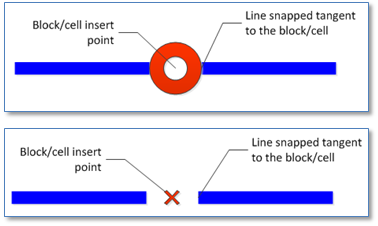
CAD snapping capabilities are similar to but slightly different than snapping performed in ArcGIS. One of the principle differences is that in CAD “point” features are often represented as “Blocks” or “Cells” that are collections of primitive entities – lines, polygons, text, etc. – and that CAD snapping agents can snap to points on the perimeter of those entities. A result we see is that lines in the CAD drawing may be snapped tangent to a Block/Cell rather than the insert point, so that when we turn off the Block/Cell we see a gap between the perimeter and insert point, as shown below.
An ArcGIS network wants lines to snap to the insert point. Numerous routines have been developed by many companies over the years to account for this gap. And in many cases its straightforward to handle.
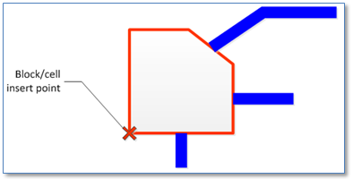
But if you think of some of the Blocks/Cells in your symbol library it may be that some cases are trickier than others. Below is an example. Here we probably would not use the insert point of the Block/Cell, but rather get the centroid of the geometry and snap surrounding lines to the centroid point.
You can also probably think of trickier examples. We certainly can, but won’t spend time with them here. The point is, in preparation for your migration its worthwhile to look at the conventions you’ve got in place for snapping from lines to equipment that should be connected in your network and see if anything stands out.
Lines snapped tangent to poles or other structures
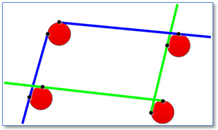
A variation on our snapping theme, let’s look at another common case where lines are snapped tangent to Blocks/Cells, but not to one another as we would hope for an ArcGIS network. To the right is a not-so-unusual case in point.
The conditions at the upper left and lower right poles are sometimes referred to as “undershoots” and “overshoots.” And while visually it may seem clear what needs to be done, these conditions are not simple to address in a completely automated manner. As a first step we could try to apply simple snapping with a large tolerance using the ArcGIS “Build Geometric Network.”
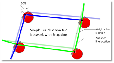
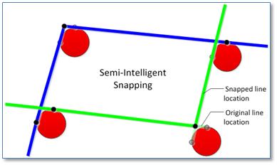
As shown to the right, the result in this case is that line end-points are connected to one another at a point mid-way between one another. This could provide a satisfactory cartographic result (depending on your expectations) – but, assuming lines in blue and green are part of different feeders, will not provide correct network connectivity.
We might want to apply a little more intelligent process, using knowledge about the lines, such as a feeder designation. Three basic rules that we might apply in the situation above might be:
- Lines of the same feeder that connect to (are within a designated tolerance of) the same pole that intersect one another should have end-points moved to their point of intersection
- Lines of the same feeder that connect to the same pole that do not intersect, but when extended intersect, should have end-points moved to the point of intersection
- Lines of different feeders that connect to the same pole should not be adjusted in any way
Results of these rules on the original example are shown to the right.
While application of rules such as those described above will likely result in an overall more satisfactory result it will also be the case that some conditions will not be handled as desired and there may well be some manual clean-up required.
The upshot of this discussion is that we need coincident end-points for ArcGIS connectivity. Anything that can be done to support this in the source material will help the process.
Devices offset from utility lines
It may be the case that devices in your CAD drawings are snapped to lines, but we’ve seen plenty of instances where this is not the case, an example is shown to the right. Again, like line end-points, devices must be snapped to lines to establish connectivity in the ArcGIS network.
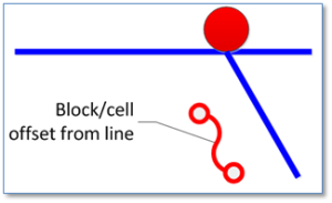
What we do will be based on the type of device and how exactly its situated. If the device to the right is, for example, a fuse then we’ll need to ensure it gets snapped to the primary tap line.
If the device is a transformer then we may want to snap it to an adjacent primary, or potentially, extend a new “connector” line to the transformer location from the adjacent primary. Any direction for this case would need to account for how secondary/service lines are represented.
CAD Layers/Levels
Mapping CAD entities to GIS features is not simply a matter of associating a CAD layer with a GIS feature class. Multiple types of equipment can be present in a given CAD layer — either by design or not. To map our CAD entities to GIS classes we need to look deeper into the differences between the CAD and GIS data models.
The CAD Entity Model
CAD drawings are stored as single files on a file system (though your implementation may include a collection of drawings organized by tile or by feeder or some other scheme). 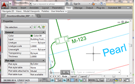 An individual file contains a set of graphic entities. An entity can have a geometry type of point, various types of lines, inserts (blocks) and text. CAD entities also have properties such as layer, color, linestyle, thickness and so forth. While the CAD ‘layer’ property can sometimes be used to serve the same purpose as a Geodatabase feature class – it does not necessarily do so. For example, CAD entities on a single CAD file layer may include those with geometry types line, point and text.
The ArcGIS/ArcFM Feature Model
Within an ArcGIS Geodatabase geographic features with distinct characteristics are grouped into separate feature classes. 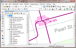
Each feature class has a set of fields (attributes) and is stored in a distinct database table. Geometry types supported for Geodatabase features include point, line, and polygon (annotation text has a line geometry type). All features in a feature class share the same geometry type. For example, if the feature class holds gas mains defined as polylines then all members of the class have gas main attributes and are defined with a line geometry.
So, back to our point. CAD Layers != ArcGIS Classes (that’s “not equal”). Or at least they may not be. This can be a particularly thorny item that you may be able to simplify with some pre-processing. If we know, for example, that all pole entities are on a layer named POLE or that all valves are on a layer named VALVE or all fiber slack loops are on a layer named SLACKLOOP then the migration process and the QA process will be simpler for everyone.
Attributes
Properties of equipment represented in your CAD drawing may be defined in a variety of ways, and if your system is long-established it may not be possible to change it for the convenience of migration.. but it may be. So, here we’ll review three standard ways you may have attributes represented and what can and possibly should be done.
Graphic Text
This is probably the simplest to create in the CAD drawing, and the hardest to migrate. In the example below we’ve got a manhole entity with the manhole number defined as a piece of text located nearby. While visually easy to interpret, the relationship between the entities is somewhat informal. 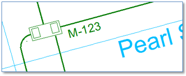 To associate these things we’ll need to perform a spatial search around the manhole to find a piece of text that contains a manhole number. If you’ve got data like this, then among the things you might consider to prepare for your migration are:
- Ensure that text holding a distinct attribute is on a distinct layer
- Position the text so that it can be unambiguously linked with its associated feature by spatial search.
Block Attributes
Block attributes provide a more rigorous method for associated attributes with a CAD entity. These can be mined by a migration process usually with good success – and much more reliably than simple graphic text. A few things you might consider in preparation for your migration are: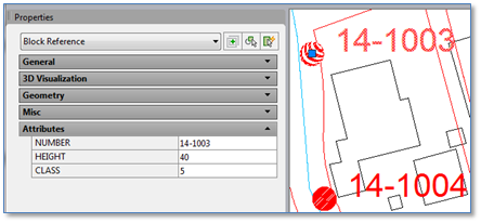
- Make sure values in the block attributes have values in the expected ranges. For example, pole heights might be numeric values from 25 to 80 in 5 foot increments. Of course, if any don’t they will fall out in the migration process, but you may want to check beforehand.
- Make sure the block definitions are consistent. For example, you might have one pole block with text displayed to the right of the pole, “POLE-R,” and another with text displayed to the left, “POLE-L”. The migration would likely want to treat these the same, so the attributes for both blocks should be the same.
Extended Entity Data
While block attributes are great, they can only be associated with, well, blocks. But some equipment is represented by lines or other entities that are not blocks. For this, AutoCAD provides the ability to associate attributes with any type of entity using a technique called “Extended Entity Data”. 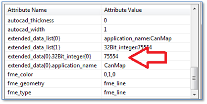 This is a bit more complicated and must be associated by an application registered to your AutoCAD drawings. To the right is an example of extended entity data as viewed through the FME “Universal Viewer.” In this case the extended entity data consists of a key value that links the entity to a record in an associated relational database – which is of course very useful.
If your data is like this then the kinds of things you’d want to check are that all entities that should have extended entity data actually do, and that if values are to hold keys to related database records there are 1) no duplicates and 2) related records exist for each key value.
Summary
This post is a little long, but really one could write a book on the topic. Hopefully its brought to light some of the most important aspects of migrating utility data from a CAD environment into an ArcGIS/ArcFM Geodatabase.
