Multiple ArcGIS Feature Geometries
Background
There are some business cases that call for multiple depictions of mapped features based on the anticipated use of the data. We’re not talking here about something like “white space management” that’s provided for placement of text labels, but rather different persisted locations for features (typically line features) based on the normal display scale of the anticipated user.
Here’s a typical example. On the below left we see underground conductors placed in close proximity to the ductbank in which they’re actually contained. The display is 1:600. When zoomed in to a scale like 1:100 distinguishing one conductor from another is clear. At 1:600, not so much. On the right is a display at the same scale with conductors spaced out. Some might consider this to be a “geo-schematic” representation.
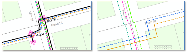
For uses such as construction design or inspection the display at the left might be fine. But for uses such as outage management where the user must operate at a smaller scale (zoomed out farther) to understand what’s going on in the vicinity, the display on the right is much more productive.
Now, many utilities avoid this conundrum in one of several ways. Among them:
1. For electric utilities with a predominance of overhead lines, well, finding a pole is quite simpler than locating a downtown, underground cab le. Thus, overhead lines, even in the case of parallel circuits on the same pole line, can be offset for readability without much danger of crews losing track of where the lines are.
2. Any utility with underground lines may take the point of view that a precise “absolute” location of the line with respect to the earth’s surface is not as important as its relative position to observable surface features, and as a result rely on dimension lines to inform crews of line locations while using a cartographic convention such that lines can be seen and distinguished even when zoomed out to a small scale.
However, some utilities feel neither of these approaches completely fit the bill and choose to maintain multiple geometries for different business needs. And, options for accomplishing this within ArcGIS are what this post is about.
In GIS History
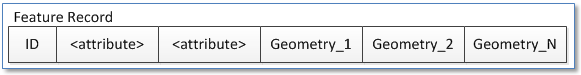
Now, if we recall some of our GIS history we’ll remember that previous utility mapping systems supported this requirements by at least logically including multiple geometry fields on the same class, as illustrated below. In this case our conductor features above could have one precisely placed geometry typically viewed at scales around 1:100 and another geometry for viewing at scales of 1:600 or smaller.
ArcGIS accomplishes the same thing in one of several ways.
ArcGIS Schematics
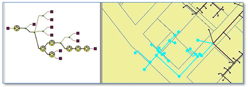
As defined in ArcGIS documentation schematics are “simplified representations of networks” intended to make complex arrangements of network features more understandable. Below is an example of a hierarchical presentation of a portion of a sewer network. The original and schematic definitions of the feature are related and one can be selected from the other. The presentation achieved by ArcSchematics can be very useful in multiple business use cases, but may not produce the type of geo-schematic expected to support all types of application requirements.
ArcGIS Cartographic Representations
ArcGIS “Representations” allow the user to create an “override” geometry for a given feature. This geometry is stored in the Geodatabase and available for any user to see. When a representation is created for a given feature class the representation geometry is the same as the original feature geometry. From there, the user can apply different symbology rules so that representations and displayed differently than the source feature.
However, the override geometry can be used to describe a distinct location for the feature. In the example below the original feature geometry is shown in magenta and the representation override geometry in dashed lines with colors based on the assigned feeder ID. Selecting a feature results in that feature being added to the selection set. Selection the representation results in the feature and the representation being selected.
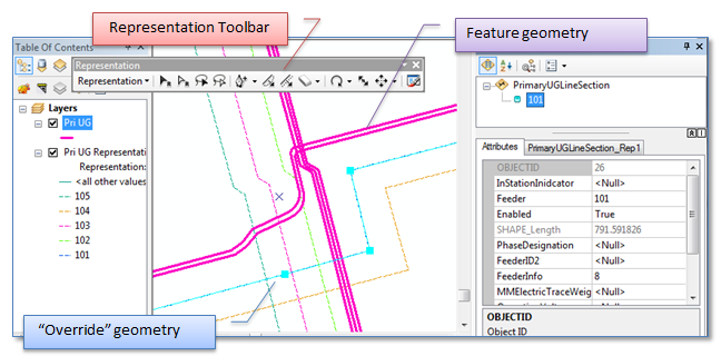
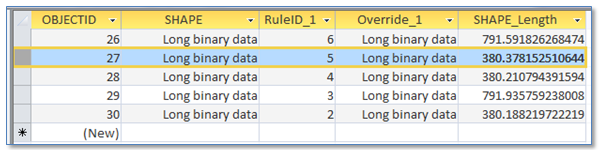
Like our historical example discussed above, the “override” geometry is stored on the same record as the feature. In the screen shot from a personal Geodatabase below, in this case the geometry is stored in the field “Override_1”. There can be multiple representation classes for any feature class.
Other characteristics of ArcGIS representations are:
- The override geometry of a feature representation is like a “graphic” that’s associated with a feature. It doesn’t have attributes of its own.
- The lifespan of the override geometry is tied to the lifespan of the feature. Delete the feature and the override geometry is deleted. Delete the override geometry and the feature is deleted.
- Selection and editing of representation override geometries is managed using tools on the “Representation” toolbar. You can’t select a representation geometry using the editor selection tool and you can’t select a feature using the Representation toolbar.
- Interestingly, using the “Identify” tool (either ArcMap or ArcFM) to click on the override geometry, results in the feature geometry being highlighted and the feature being included in the identify list.
Related Feature Classes
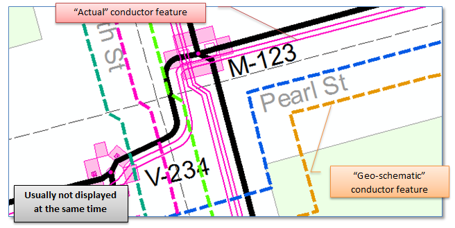
Finally, we can create multiple, related feature classes to hold distinct geometry depictions. An example approach we’ve exercised with success is to create a class in the electric geometric network using the “geo-schematic” conductor geometry and class with “actual” conductor locations that contains nothing but a geometry (shape) and foreign key to link it to the corresponding feature in the “geo-schematic” class. All devices are connected to the “geo-schematic” conductor geometry, and of course all traces are performed on this class.
Some advantages we found to this approach included:
- The same selection and editing tools from the standard editing toolbar could be used to select and operate on both depictions of the conductor.
- With a composite relationship defined from the “geo-schematic” to the “actual” conductor classes deleting a network feature would delete the non-network feature. We did not necessarily want deletion of the “actual” feature to delete the network feature.
- The same tools governed display and identification of both feature classes.
Summary
From our experience, evaluation and understanding of approaches taken by utilities using ArcGIS software, either ArcGIS Representations or Related Feature classes provide suitable approaches for display and maintenance of multiple depictions of feature geometries as “geo-schematics” – if such functionality is required. ArcSchematics can be great if you are looking for an auto-generated schematic depiction. Your choice will depend on your specific needs and expectations.