Loading Fiber Optic Cable into ArcFM Fiber Manager
The foundation of a ArcFM Fiber Manager implementation is the Fiber Manager “flexible data model.” This affords considerable latitude to an implementer to organize data in the way that best suits her organization, and still can take advantage of all of Fiber Manager’s rich set of functionality.
One of the first steps in an implementation is to get data into this model. Depending on the nature of the source material, the best course may be to heads-up digitize cables, splices, patch locations and other features with reference to source material and spreadsheets. However, if the organization has electronic data in a standardized format then it may make sense to perform an electronic migration. This case study will talk about the case where you do have electronic data for fiber cables, including cable geometry and attributes, and how you might go about migrating that data into a form expected by ArcFM Fiber Manager.
Here first are several assumptions about your source data:
- The source data has a geometry type you can easily read. This means it’s a shape file, or line feature in a personal geodatabase or file geodatabase, or even a ArcInfo 7.x coverage. Or it may be data in some other format that you have tools to read.
- There are attributes associated with each cable including at minimum the count of fibers (and possibly buffer tubes) present and a field that can be used to assign a cable name.
- Finally, the geometries all begin and end at some piece of fiber optic cable equipment. While this won’t matter for the current case, but ultimately Fiber Manager expects this to be the case. In other words, there shouldn’t be cases where we create “generic junctions.”
Given those assumptions about the source data, here are important characteristics of the Fiber Manager cable model.
- A fiber cable is represented as a complex line feature with attributes including fiber count, manufacturer, twist factor, glass length and so forth. This class is named FiberOpticCable. The attributes we can assign automatically will depend on those present in the source.
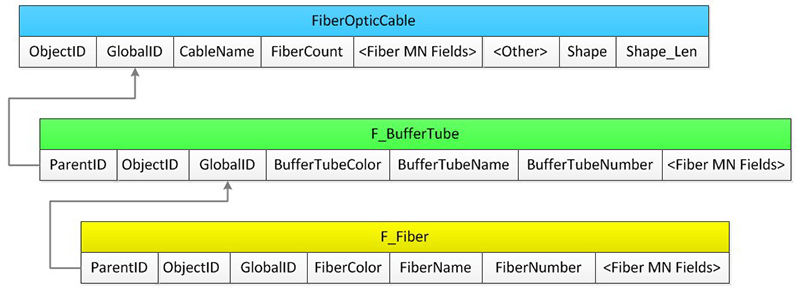
- Just as a fiber cable encloses a set of buffer tubes, the Fiber Manager model has a table named F_BufferTube with one record for each buffer tube present in cable. Buffer tube records are related to the parent fiber cable by a foreign key field named Parent, which holds the cable’s GlobalID value.
- Finally, as a buffer tube enclosed a set of fiber strands, the Fiber Manager model has a table named F_Fiber which is related to the buffer tube again by its GlobalID value.
Below is a simplified representation of the relationships.

With that, here’s an overview are the steps for migrating your source data into the fiber manager model from within an ArcMap session.
1. Create the FiberOpticCable Feature
What we need to do is create a cursor on the source class and iterate over all features. We’ll get the geometry from each feature and assign it and any know attributes to the target. After each feature is created with get the GlobalID assigned and use that for creating our buffer tubes.
Here are assumptions about what has been done prior to us getting to this point:
- We’ve got references to the source and target fiber cable classes
- We’ve got field indexes for the fields we’re going to get and set
- The source and target classes have the same spatial reference, “SR.” (If they don’t all we would have to do is get the SR of the target class and project the geometry of each source feature before assigning it to the target.)
- We’ve started editing and we’re inside an edit operation
For brevity we’ll show only that code directly involved in creating cable features, in practice you would include error handling and standard coding techniques to ensure robustness.
2. Create the Buffer Tubes within the Fiber Cable Feature
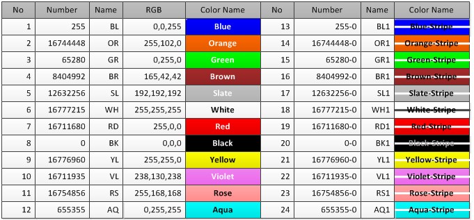
Once we’ve created the fiber cable feature we’ll now create buffer tube records. In this example we’ll use a simplifying assumption that all tubes contain 12 fiber strands. We’ll also assume that we can look up buffer tube colors and names based on standard industry conventions. The routine GetColorAndName will look-up values in a table such as that below.

3. Create the Fiber Strands inside the Buffer Tube
Finally, we’ll create strands inside the buffer tube. In this case assigning the buffer tube GlobalID to each fiber strand as a foreign key. We’ll also use the same GetColorAndName routine to look up a color and name as we used when creating the buffer tubes.
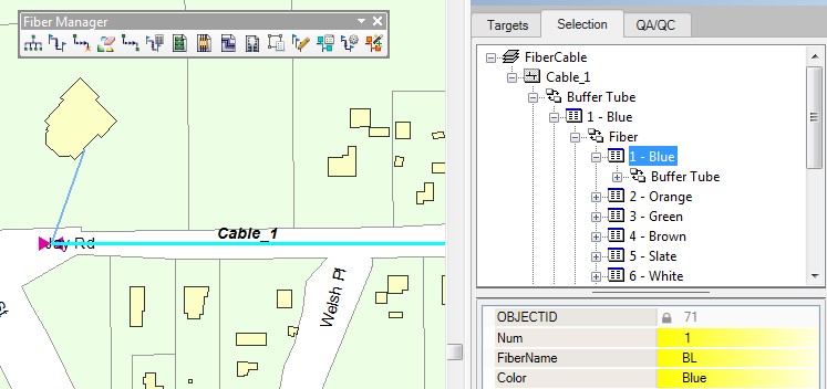
Build and execute your ArcMap command or Add-in and you’ll be creating fiber cable with buffer tubes and fiber strands, just like the example below.

Creating fiber cable and the contained buffer tubes and fiber strands is just one of the steps you’ll need to follow to get your Fiber Manager implementation off the ground, but hopefully this case study can help you get started.
Fiber Manager Model Names
In keeping with the intent of the “flexible” data model, and really with the ArcFM Solution as a whole, the class can be named anything you want. Name it “FiberCable” or “Cable” or “Joes_Excellent_Cable” if you’d like. The important part is that the class be assigned the class model name “SHEATH.” This applies to all feature classes and all tables in the model. It also applies to all fields of significance to the Fiber Manager software.
Fiber Manager Relationships
All relationships in the Fiber Manager model are based on row GlobalID values – which are stored as the data type GUID (Globally Unique Identifier). Among other things, this makes the database entirely portable, so that if you export you Fiber Manager database from, for example, a SQL*Server instance to a File Geodatabase you can be assured the relationships will remain intact.


