Automating (parts of) ArcFM UFM Data Migration
The ArcFM Underground Facilities Manager (UFM) tools provide a great way to manage the many details and associations present in a major underground facilities network. Typically the source data (or at least much of it) is not in a form that can be loaded by an automated migration process. Rather, important details to be captured – such as manhole wall duct packages and associations between ducts and cables – exist only in paper form or photos or scanned images in an electronic some other form that does not lend itself to ready migration. These components usually must be created using UFM tools — which is why those tools were created in the first place.
There are however several components that can in some cases be automated. This post will address migration of UFM Wall, UFM Floor and Conduit System features given some key assumptions:
- There is a source dataset with representations of underground structure polygons and conduit system paths from structure to structure
- This source dataset is either in the same projection as the target Geodatabase projection or that a reasonable transformation can be applied to put these features in the target projection
Migrating the UFM Floor
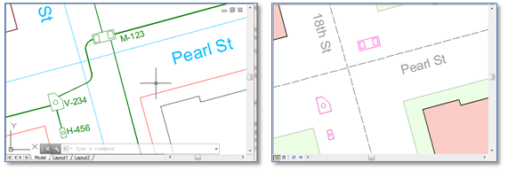
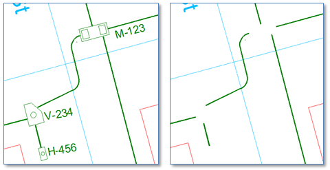
Here we’ll assume the source data has a representation of the manhole or vault or handhole extent in the form of a polygon, or a CAD block or cell. In this case we’ll use a tool like FME from Safe Software to convert the floor polygon geometries to a staging location. Example results are below with source CAD data on the left and ArcFM features on the right.
We’ll need to make sure to use the option to “explode” individual elements of the blocks/cells in our source data. Further, if the source entities contain multiple parts per feature then it may be necessary to aggregate these into a multi-part polygon geometry.
Getting a Facility ID Value for the Floor
The most important attribute within the whole UFM toolset is the “FacilityID”. UFM requires this field be present and populated on the UFMFloor, UFMWall and UndergroundStructure feature classes and uses is to assemble all parts of the underground facility.
In our source data there may be an attribute of the manhole block/cell that will give us a facility ID value, but it’s more likely that, if present at all, the identifier will be a piece of text located close to the structure. If we’re very lucky each individual piece of text will be closest to the actual structure it identifies. And in this case we can use a spatial query (of FME “NeighborFinder” transformer) to associate the text with the UFM floor feature we just created.
More likely however, there will be cases where the ID text is not placed closest to its structure, but rather is placed in a location that does not obscure other underground equipment and is convenient for the reader but in terms of actual proximity is closer to another structure. In these cases some manual intervention, such as moving text entities inside the source structure polygon, will be required.
Creating an UndergroundStructure Point Feature from the UFM Floor
If your source data has the manhole floor described as a polygon chances are there will not also be a point feature that UFM will need to represent the UndergroundStructure feature. There are several ways to go about this task.
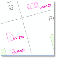
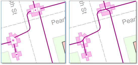
One way would be to use FME again to export the floor geometries, but this time do not choose the “explode” option, in which case we’ll get insert points for each source block/cell. Depending on how the block/cells were defined, this provide completely satisfactory. However, if for example they were defined such that the insert point falls on the perimeter of the polygon (examples of which are illustrated on the right) or possibly even outside the polygon, then we may need to go to “plan B” which would be generating the UndergroundStructure point geometry from the centroid of the floor polygon.
In ArcObjects we would just get each polygon geometry, cast it to an IArea object and get the centroid point from the IArea. In the event the polygon geometry is multi-part (as in the case where the manhole cover or other entryway is included in the source polygon block/cell) we just need to remember to get the centroid of the most exterior ring of the polygon geometry.
But however we get this point we need to make sure we assign the FacilityID value of the UFM Floor feature from which it was created.
Creating the UFM Wall Features
The feature class UFMWall is used to represent each inside wall of the underground structure and is typically created as a rectangle adjacent to each exterior segment of the UFM Floor polygon.
Given a known or assumed wall height (which could be different for different types of underground structures), these UFMWall features can be created for each floor by constructing points offset from the begin and end points of each floor segment and assembling a polygon from the perimeter endpoints and the constructed offset points. Note that the direction in which wall vertexes are created is quite important as ArcGIS expects polygons to be counter-clockwise, otherwise you might get your polygon fill symbol leaking into the rest of your map display.
Again, as with the underground structure we created in the previous step, we need to make sure that the Facility ID value for the structure is assigned to each wall polygon that we create.
Creating the Conduit System Features
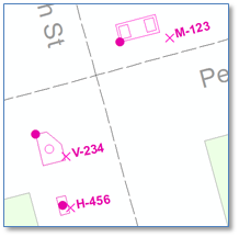
UFM expects an underground structure network of conduit system edge features and underground structure junctions, with edge end-points snapped to underground structure features. While snapping to underground structure insert points is important and valuable within the UFM world, conduit lines are not typically drawn this way in source dataset. Rather, the conduit is often drawn snapped to the manhole polygon perimeter, as illustrated below.
To take advantage of UFM tracing we’ll want to extend each conduit at each connected manhole and snap it to the UndergroundStructure feature we had created in the previous step. This can be done by finding the UFM Floor feature closest to each end of the conduit system line, then finding the underground structure feature inside that UFM floor, and adding a vertex to conduit system line so it snaps to the underground structure point feature. You might consider instead of extending the existing line to create a distinct new conduit system line from the floor perimeter to the center point, but if you do users exercising the UFM functionality for traversing from one manhole to the next will have to apply multiple clicks to get there. If curious you might just need to try it.
If our model has a relationship from conduit system line to underground structure, this is a good point to establish it.
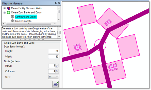
Adding the Ductbank Packages
When it comes to adding details of duct bank packages and individual ducts within those ductbanks, and then associating the duct bank packages with conduits and ducts to conductors contained within the ducts, that’s really where the UFM Diagram Manager tools come in to play.
Summary
With that, we’ve got a solid start on the UFM data migration process and have components of a dataset ready for use with the UFM “Diagram Manager” tools that will be used to complete creation of duct packages and relationships to conduits and conductors.