ArcFM Feeder Manager Feeder Head (AKA Circuit Source)
ArcFM Feeder Manager (both 1 and 2) keep track of energized equipment fed from a “head” or “source,” which is established in your ArcFM Geodatabase by a relationship to a row in a table with the CIRCUITSOURCE model name. Interestingly, different companies choose different devices/locations to designate the feeder head. Another case where while equipment in the field varies little from company to company, the way companies have chosen to represent that equipment in their GIS can vary quite a bit.
This post will describe conventions we’ve seen adopted. The choice of approach is typically driven by data availability or historical convention. Where otherwise the driver is noted.
At the Circuit Breaker
Nominally you would expect this to be the case. The most upstream protective device would be a logical choice. But even this convention varies. The reason it varies is because companies have established different strategies for mapping equipment inside the substation versus equipment in the distribution system.
No Station Internals
When the company does *not* include station internals in its GIS then the breaker may be located at its approximate location. While the location is approximate the company provides attributes (company ID, operating voltage, interrupting rating, normal status, etc.) that describe the actual circuit breaker/circuit recloser device.
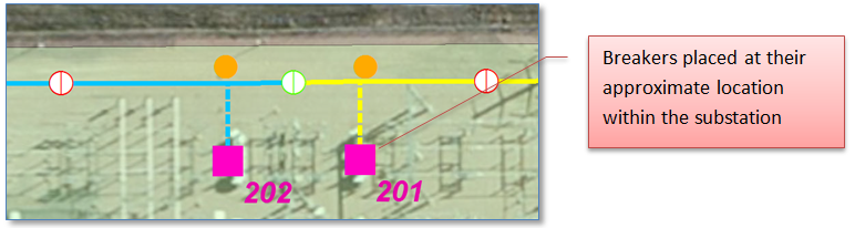
This feature *may* or may not be physically connected with upstream equipment (within the substation). If so, care must be taken to ensure it doesn’t inadvertently become part of a multi-feed. The exception being the case of “Extended Feeder Manager” — but that’s a story for another post.
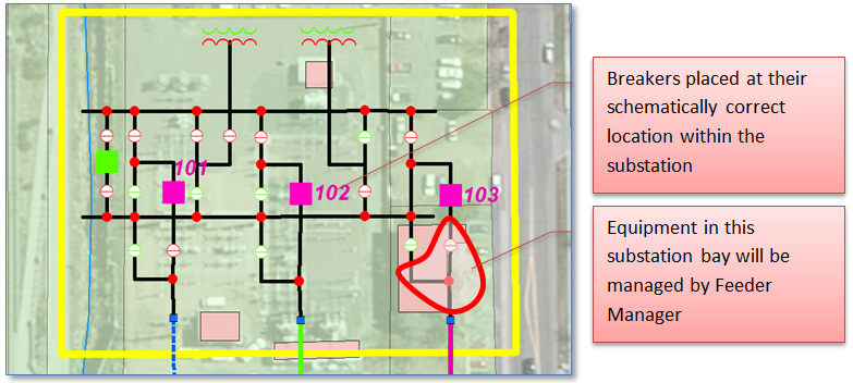
Station Internals
In this case the breaker feature is located at the “actual” location of the breaker with the configuration of station equipment. The “actual” location may correspond both to its geographically correct position as well as its location within the station topology – or simply the correct topological location, depending on the overall spatial accuracy of the database. Here features within the station downstream of the breaker will be managed by Feeder Manager.
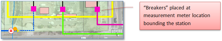
A variation on this approach would be to have another actual piece of equipment serve the purpose of a Feeder head — such as a measurement meter.
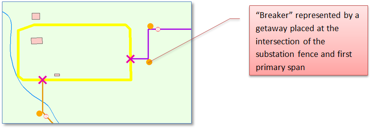
At a Station “Getaway”
In this case the company maintains no substation internals in the GIS at all – not even an approximate location of a breaker. But the company does know that a span of primary exits the sub and equipment downstream of that span are energized from the same source. Since Feeder Manager expects the “head” to be represented by a point feature the company may manufacture a point at the intersection of that most upstream primary span and the station fence and call this a getaway. The new feature doesn’t attempt to describe properties of the breaker inside the fence, but rather simply serves to meet Feeder Manager’s requirement to have a head.
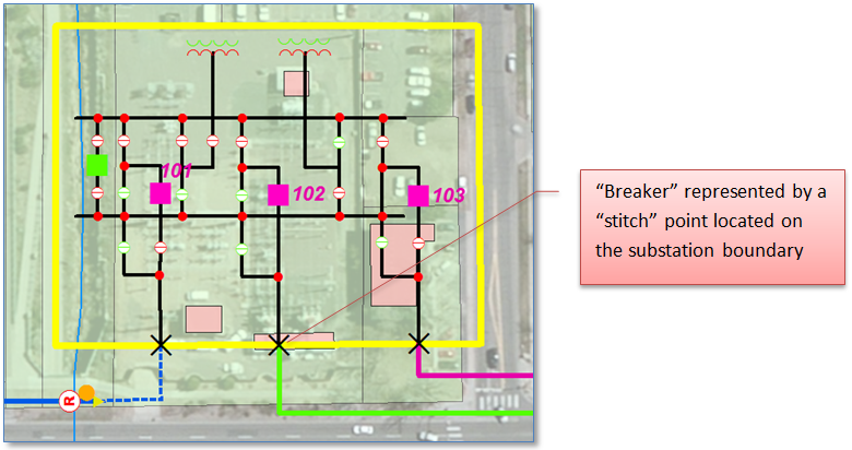
At a “Stitch” Point on the Station Boundary
In some cases the company may actually have substation internals in the GIS, however the substation internal features are maintained in a separate dataset than the distribution system equipment. Among the reasons for this would be:
- A need to provide distinct security for editing/updating substation data for example, in the event different groups within the organization are responsible for maintenance of substation and distribution equipment.
- Distribution features are exchanged with an analysis product (such as a DMS) but substation equipment is not, possibly because the analysis application maintains its own substation representation.
In this case, as illustrated below, the actual breaker would lie within the substation dataset – but as such could not be part of the same geometric network as the distribution system features. To provide a “head” for Feeder Manager use a surrogate would be defined within the distribution feature dataset at a location on the substation boundary where substation and distribution equipment are “stitched” together. It also may be the case that custom code is used to perform special-purpose tracing that navigates through the stitch point to trace between substation and distribution equipment.
Step Transformers
Of course the definition of what constitutes a “distribution feeder” can vary from company to company. In many, probably most places the feeder includes all features downstream of the station breaker bounded by ends of line and open tie points.
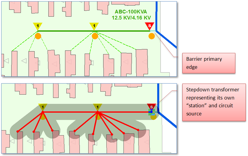
In some cases a further distinction is drawn where voltage changes from one primary voltage to another, as would happen at a step-down transformer where voltage is dropped from, say, 12.47 KV to 4.16 KV. The portion of the system downstream of the step-down would be considered a distinct feeder.
This is supported in standard models by a relationship from TransformerBank to the circuit source table. In this case the transformer with an associated circuit source record will be considered the head of the 4.16 KV feeder. Note that, unless implementing Extended Feeder Manager, you’ll need a barrier that prevents the upstream feeder tracing down into the 4.16 KV system. In the example below we use a small primary span that is assigned FdrMgrNonTraceable = True.
Mesh Networks
A similar technique to that described above for stepdown transformers can be employed for designating network transformer(s) bounding a downtown mesh network as the “head” of that system. In addition, custom tracing routines can be built that consider the network protector on those transformers as a one-way barrier allowing traces from the upstream radial primary into the mesh network but preventing traces originating with the mesh to proceed out. But that’s a story for another post.
Summary
In this post we’ve provided a high level exploration of four approaches to representing the head of a distribution system feeder, along with several variations on these approaches. There may be more, but that’s what we’ve seen. (If we run across others we’ll add them).