ArcFM Cathodic Protection — Bond Junctions
The ArcFM Cathodic Protection (CP) Manager tools provide an effective way to represent and to manage CP System in your gas or water Geodatabase dataset. With it you can inspect, navigate to, create, update and delete individual CP system features, represented as an aggregation of the line geometries of mains and services present in the distinct connected CP network.
A CP network can include mains and services, of course, and valves and fittings, as well as CP devices such as anodes (or anode beds), rectifiers, test points, wire and bond junctions. Whether or not a given pipe, fitting or valve is included in an ArcFM CP trace depends on the properties of the individual feature, in particular its material, whether its bonded or insulated and the value assigned to the special purpose CPSystemStatus field.
CP equipment, on the other hand, is generally always included in an ArcFM CP trace. In other words, CP traces do not stop at CP features.
But what if there are cases when you want them to? That’s the topic this post will address.
Bond Junctions and ArcFM Cathodic Protection Tracing
Consider the case of bond junctions that provide a termination point or junction for CP applications. It may be the case that a junction is considered a “solid” and conveys current between wires connected within the junction box – but this is not always so.
In some cases the junction may simply provide a termination for wires connected to pipes – but not connected to each other in the junction box. In which case the junction would be considered like an “open point” in an electrical circuit.
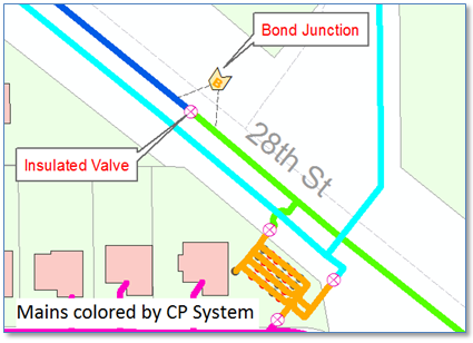
Consider the example below in which we have a portion of a natural gas distribution network with pipes symbolized by CP System name. Note that there is an insulated valve separating the blue and green systems, and a bond junction with wires spanning the valve above.
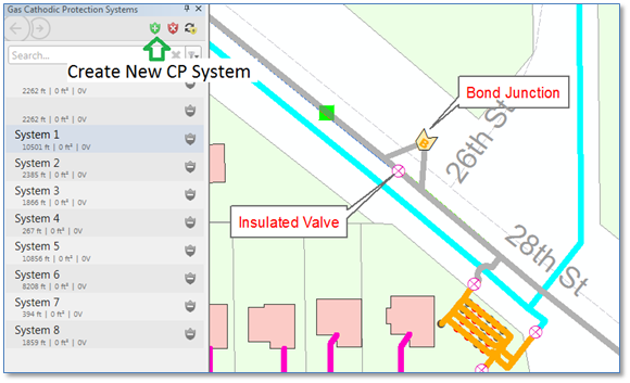
Were we to re-create our “blue” CP System by clicking on the “Create New CP System” button and clicking on a blue pipe segment the trace would proceed through our bond junction into the adjacent CP system – as we see below. But in this case we know that wires in the bond junction box are in fact not electrically connected and that current does not flow from one system to another, so this representation would be incorrect.
So… what now?
We could physically disconnect one or both bond wires to break our circuit, but that would be incorrect, too. Because we know that the wires are connected to mains on either side of the insulated valve, and that the wires terminate in our bond junction box, they’re just not connected to one another inside the box.
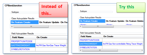
Another option is to change our ArcFM configuration slightly and make use of the CPSystemStatus field. Typically the CPBondJunction class is configured with the ArcFM class model name GASNONTRACEABLE with no CPSystemStatus field. Also, the ArcFM Auto-Updater assigned for calculating trace weight values is “ArcFM Gas Non-Gas Trace Weight”.
To enable our bond junction to either allow or prevent current from flowing through the CP network we can make these three (3) changes:
- Remove the class model name GASNONTRACEABLE and replace it with the class model name NONCONTROLFITTING
- Add a field CPSystemStatus to the CPBondJunction class and assign it the field model name CPSYSTEMSTATUS
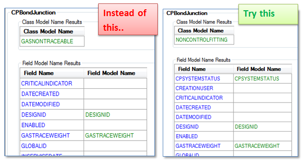
- And finally, remove the “On Create’ and “On Update” Auto-Updater “ArcFM Gas NonGas Trace Weight” and replace them with the Auto-Updater “ArcFM Gas Non-controllable Fitting Trace Weight”.
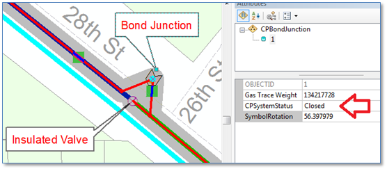
With these changes in place our bond junction feature now stops an ArcFM Cathodic Protection trace when the CPSystemStatus field is set to “Open”….
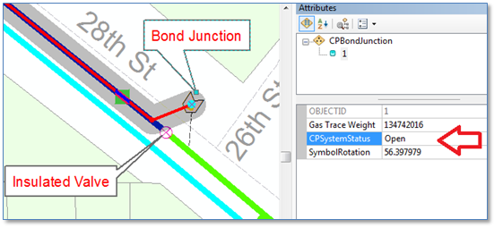
… and enables the trace to proceed though when CPSystemStatus is set to “Closed”. For further validation you can check how the GasTraceWeight value is updated using a Gas Trace Weight Inspector tool.
The CPSystemStatus Field
The CPSystemStatus field (and matching model name) doesn’t necessarily correspond directly to a single physical attribute of a piece of gas or water system equipment, rather it’s a kind of catch-all field that determines whether or not a given feature should stop a CP trace. If its value is set to [1] “Open” or [Y] “Yes” then a CP trace will stop at the point or edge feature regardless of any other properties or settings. If its value is something else, then the remaining properties(i.e., bonded indicator, insulated indicator or material) or settings (such as a network barrier) will determine if the trace will stop.
Summary
This blog walked through steps we would follow to slightly alter our ArcFM configuration to support modeling cathodic protection bond junctions to be able to stop or permit an ArcFM CP trace to proceed through. If you model bond junctions this way in your network hopefully you might find this approach of value.
