Ever perform an ArcGIS/ArcFM downstream (or upstream) trace and get results you did not expect? Unless your data is perfect (and I know of no perfect dataset) then I’m guessing the answer is “yes”. So, the next question is, why? There may be many answers — this article will describe some. Specifically, it will discuss some of the reasons why your trace did what it did – which was other than you expected – even though you thought your data was great. It will also skip the obvious cases of features clearly not snapped, or phasing not set or an incorrect normal position setting, or similar things.
“Trace returned no results”
I’ll start out with a favorite, a trace that returns the message “Trace returned no results.” Actually, there are many reasons why this occurs. For now I’ll focus on one particularly vexing condition, the full set of symptoms are as follows:
- Perform a downstream trace on a feeder just upstream of a transformer. The expected result are returned, including primaries, transformer(s), secondaries and service locations.
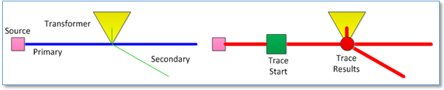
- Perform a downstream trace initiated at the transformer itself (one included in the previous trace results). The result is the message “Trace returned no results.”
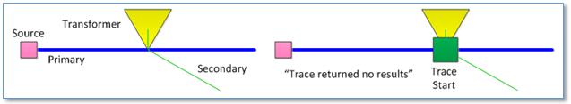
How could this be? The first trace, which completed successfully, was a “superset” of the second trace, which returned no results. Shouldn’t a trace performed within the bounds of a previously performed successful trace also be successful? Clearly not necessarily.
Here’s the difference. The first trace process started on a primary line with a valid geometry, got the geometric network EID from the line feature and dove into the logical network (LN) obtaining “forward star” cursors within the network until it completed. When trace limits were found in the logical network the set of traversed EID’s were returned and used to select and/or highlight corresponding features.
The second trace started at the transformer junction feature and examined each connected conductor (primary and secondary) to determine where to proceed. If we look closely at the secondary line we can start to see the issue. Vertices 0 and 2 occupy the same X,Y location, which ArcGIS considers to be a “loop” and which makes the geometry invalid for a geometric network edge.
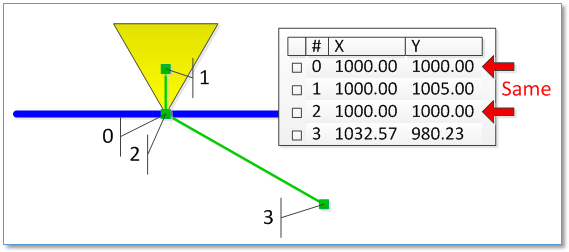
When the trace process tried to inspect this edge feature it encountered the invalid geometry and failed at that point. It never got into the logical network to begin its “forward star” querying process. Thus the trace returns a “returned no results” message.
In contrast, the first trace got from the feature into the logical network without problem and traced to and through the transformer and secondary while in the LN and returned results as expected.
“Case of the Step-down Transformer”
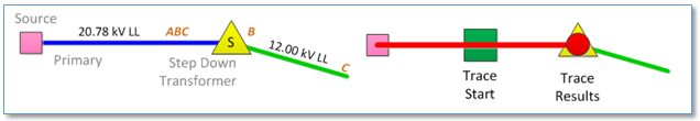
This case was initially puzzling because the trace started on a primary conductor and stopped at a step-down transformer which on the low side had other primary voltage conductors. The transformer and primaries are all connected, but under no condition would the trace proceed beyond the step-down transformer. It’s as if the step-down transformer were acting like an open switch.
Puzzling all the more because when we perform a trace in a similar condition when the primary on both sides of a standard distribution transformer are the same voltage we get the expected results. The transformer is traced, as is the downstream secondary and the downstream primary. So, what gives?
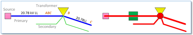
After a little rumination it’s clear that, though the 12 kV line downstream of the step-down transformer is a primary voltage, it’s a different voltage than the primary on the source side. And in this case different matters. When the first trace hits the transformer and examines the transformer’s connected phases – in this case it’s connected to ‘B’. Then it looks for connected conductors. Those with a different voltage than the upstream conductor are considered to be on the other side of the transformer and must share a common phase code for power to pass through it. Since the transformer is on phase ‘B’ and the low side primary is at 12.0 kV rather than 20.78 kV and since the low side primary is on phase ‘C’ the trace stops.
Now, this is also probably a data issue and the transformer (and possibly to low side conductor) phasing may not be correct.
“Secondary snapped to a primary without a transformer”
This one seems pretty straightforward – when you finally find it. But tracking it down can be a chore. The issue, as illustrated below, is where a secondary ends up getting snapped to a primary where it shouldn’t. The case below is a relatively dramatic one in that the secondary ends up connecting two separate feeders otherwise separated by a normal open, but the case where the secondary snaps directly to a primary that part of the same feeder also creates a loop – and creates a problem.
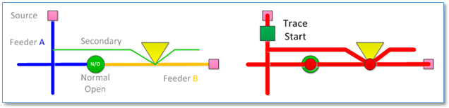
Of course, all elements in the above scenario would be considered to be in a “multi-feed” condition. Use of the ArcFM “Bit Twiddler” layers can be of some help in this case. Also helpful can be use of ArcGIS connectivity rules. In this case the connection of a secondary to a primary at a “generic junction” would violate the connectivity rule and return a QA error.

Bookmarked! Great website.